Module 3 - Configuring the CU
Introduction
Configuration of the OptaSense Control Unit (CU), either as part of a new system or if being added to an existing one, consists of the following tasks:
- Preparation
- Create a bootable flash drive with OptaSense Windows image
- Setup BIOS
- Installation and authentication of the OptaSense configured Windows Operating System.
- Configuring the CU
- Set IP address as per Network Diagram
- Set date/time
- Network Bandwidth Verification
Preparation
Before configuring the CU, ensure that it is not connected to the Internet. If connected, Windows may automatically start downloading updates which may disrupt the installation process and risk an incomplete installation.
Creating Bootable Flash Drive with OptaSense Windows ISO
The first step is to acquire the latest revision of the OptaSense configured Windows 10 operating system from the Software Issuing Office and create a bootable USB.
- Download OptaSense Windows ISO
- Insert USB Flash Drive – minimum 16GB
- Download and run Rufus software
- Under the Device section, select the USB Flash Drive that you have inserted
- Click the SELECT button and select the Windows ISO that you have downloaded
- Make sure the options are as follows:
- Partition scheme – GPT
- Target system – UEFI
- File system – NTFS
- Click START to start creating a bootable flash drive
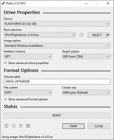
Figure 1: Rufus Installation Screenshot
BIOS setup
The BIOS settings of the CU need to be tailored so that if there is a power loss, the CU will return to an ON state. The following steps need to be followed to achieve this:
- Power on the CU.
- During boot, press F12 continuously to enter the BIOS setup. If using a Rack-mounted CU, press Delete instead.
- Change SATA Configuration to AHCI
- System Configuration > SATA Operation > AHCI
- Turn off Secure Boot
- Secure Boot > Secure Boot Enabled > Disabled
- Boot Mode to UEFI
- General > Boot Sequence > UEFI
- Ensure Local Drive – where the operating system will be installed – is before Flash Drive with the Windows image
- General > Boot Sequence > Use up and down arrives to change order, top items have the highest priority
- Save changes and exit
- Apply > Exit. If using a Rack Mounted CU, press ‘F4’ instead
Installation of the OptaSense Windows Image
- Boot from USB Flash Drive
- Invoke the boot menu (Figure 2) by pressing F12 as the computer boots up. If Rack Mounted, press F11.
- Select the bootable USB Flash Drive from the list of boot options. If “USB Flash Drive” does not appear, it may appear as an option with “USB” and the brand of flash drive.
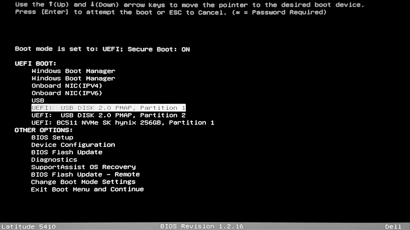
Figure 2: Boot Menu
- Follow Windows Installation Process
-
Select Language, Time and currency format, Keyboard or input method and select next (Figure 3)

-
Figure 3: Windows Language and Other Preferences Window
- Select drive to install Windows
- Select the primary hard drive as the location for the Windows installer (Figure 4).
- If there are multiple partitions, erase them. Note: deleting a partition will delete all the files on that partition.
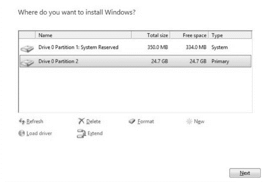
Figure 4: Installation Drive Selection Window
- Press Next to begin the installation process (Figure 5). This should take about twenty minutes and the system will reboot several times during the process.

Figure 5: Installing Windows Progress Window
- Following the Windows installation, several OptaSense scripts will run automatically to install additional applications that are included in the OptaSense windows build.
- Once the installation is complete, login to Windows.
- Apply the Windows Licence Key and associated AMT stickers neatly to the CU unit.
Configuring the Control Unit
Setting the IP address of the CU
The IP addresses of the CU needs to be changed to reflect the approved Network Diagram (ND). The IP addresses can be changed in the Network and Sharing Centre within the Control Panel. Note, both network cards may need IP addresses.
- Right-click on network connections section located on the right-hand side of the toolbar and select Open Network & Internet Settings
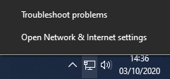
Figure 6: Windows Task Bar
- Under Advanced network, Settings click Change adapter options
- Select the network interface that you would like to edit, right-click, and select Properties
- Highlight Internet Protocol Version 4 (TCP/IPv4) and click Properties
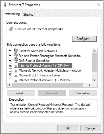
Figure 7: Network interface properties
Setting the Date and Time to System NTP
All OptaSense 6 systems are installed with a Network Time Protocol (NTP) device. This can either be supplied by OptaSense or by the end-user. The IP address for the NTP can be found in the ND.
To configure:
- Right-click on the time and date located in the bottom right of the screen
- Select ‘Adjust Date/Time’
- Select ‘Add clocks for different time zones’ on the right-hand side to open a pop-up window.
- Select the ‘Internet Time’ tab
- Select ‘Change settings…’
- In the Server text box, enter the IP address of the NTP and select ‘Update Now’
- Confirm the date and time has been synchronised with the NTP.
Activating Windows
-
Open Window Search, type Settings and press Enter.
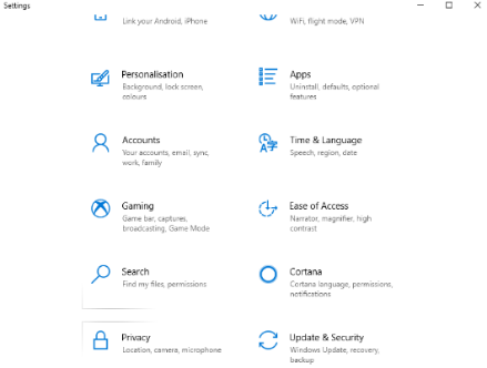
Figure 8: Settings Page
-
Select ‘Update & Security’ This will bring up the update and security window within this window the activation status can be viewed. Note, If Windows is already activated skip the following steps.
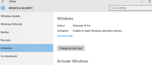
Figure 9 : Windows Activation Window
- The majority of the new Dell PCs already have a W10 product key installed. To retrieve the preinstalled Windows 10 product key:
- Open a new command prompt window.
- Type the following command:
- wmic path softwarelicensingservice get OA3xOriginalProductKey
- If Windows still requires activating, select the link ‘Activate’. If the CU is connected to the Internet a pop up will appear asking ‘Activate Windows Online’ select this and Windows will automatically activate itself online.
Completing a Control Unit configuration
Following successful completion of the Window’s installation, the Control Unit will require some first time bootup configuration and must be configured in accordance with the Client Configuration Variables Profile and the installation of OptaSense OS6.
Detail on the customisation of the Control Unit can be found in:
- OptaSense OS6 Manual Module 5: Installing OptaSense 6
- OptaSense OS6 Manual Module 6: Configuration Wizard User Manual.
The Client Configuration Variables Profile is a client and project specific publication derived from an OptaSense template. For more detail consult the relevant project manager.
Note: These actions can only be completed once you have a full working and installed system.
Network Bandwidth Verification
To ensure that the network provided by the client is running as required, it is necessary to run some simple bandwidth analysis tests as part of the installation procedure. One of the main reasons for running additional tests is that the data provided by Ethernet testers often doesn’t tally with real operating conditions.
The Network Bandwidth software that OptaSense currently uses is installed on the network nodes as part of the OS, the Control Unit test script can be downloaded from the following link.
The required bandwidth for your project should be found in your project documentation or consult your project manager.
OptaSense uses a distributed database and so even before OS6 is installed there will still be network activity. The scripts should be run BEFORE OptaSense has been installed and the database configured. The scripts can still be run after installation but expect a modest amount of background traffic.
NOTE: If you are running the scripts after OptaSense has been installed. Ensure that all processes have been stopped via the GUI.
Instructions for use
It is critical that the network backbone is tested for all nodes in the system. To conduct further testing use the following procedure: Network Bandwidth Testing.